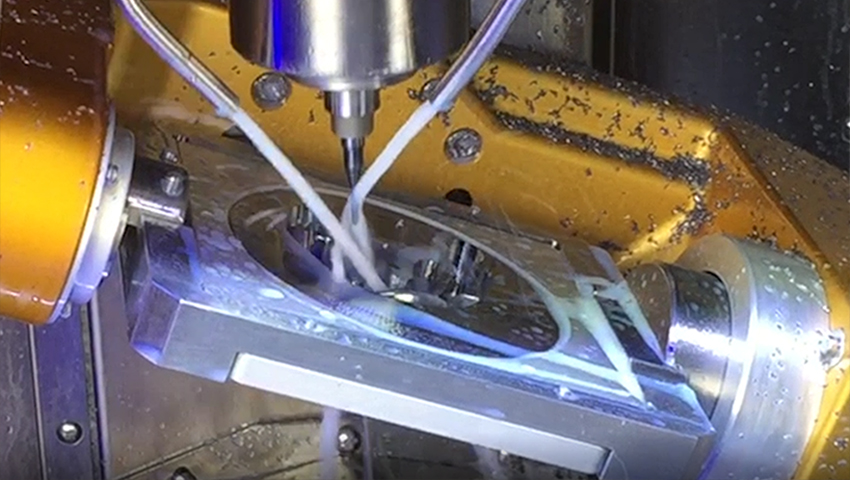
Automated 5-axis Processing
Undercut Machining
Machine Complex Bridges, Dental Bars & Implant Abutments Not Otherwise Possible.
Contact Us Purchase now !Intelligent & fully automated 5-Axis processing provides greater accuracy, higher-quality finishes & reduced hand-finishing.
The Basics
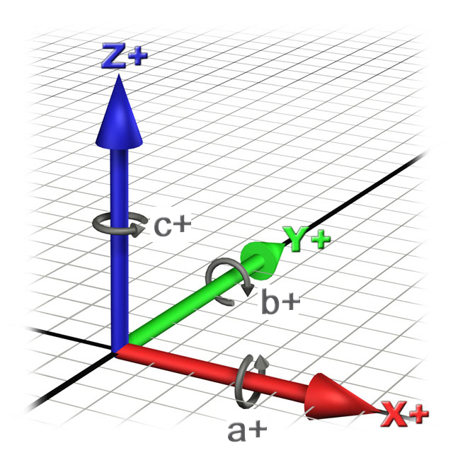 Generally Speaking, 5-Axis machining is a manufacturing process where computer numerically controlled axes moved in 5 ways are used to manufacture parts out of metal or other materials by milling away excess material. Typical CNC tools support translation in 3 axes; multi-axis or 5-axis machines also support rotation around one or multiple axes.
The number of axes for multi-axis machines varies from 4 to as many as 9. Each axis of movement is implemented either by moving the table (into which the workpiece is attached), or by moving the tool. The actual configuration of axes varies; therefore machines with the same number of axes can differ in the movements that can be performed.
Generally Speaking, 5-Axis machining is a manufacturing process where computer numerically controlled axes moved in 5 ways are used to manufacture parts out of metal or other materials by milling away excess material. Typical CNC tools support translation in 3 axes; multi-axis or 5-axis machines also support rotation around one or multiple axes.
The number of axes for multi-axis machines varies from 4 to as many as 9. Each axis of movement is implemented either by moving the table (into which the workpiece is attached), or by moving the tool. The actual configuration of axes varies; therefore machines with the same number of axes can differ in the movements that can be performed.
5-axis machining can be broken down into two different categories; full, simultaneous 5-axis machining and 3+2 5-axis machining.
Simultaneous Motion
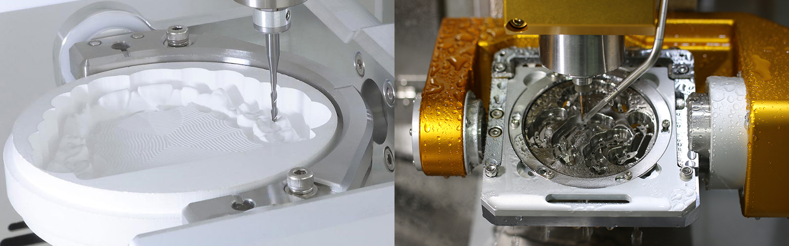
In simultaneous 5-axis machining, the machine tool’s three linear axes (X, Y and Z) and two rotational axes (A and B) all engage at the same time to perform complex contour surface machining particularly important in the finish machining of undercut areas. There are many advantages of full 5-axis machining, all of which significantly impact finished product quality, productivity and profitability.
- Solution should detect undercut areas and generate smooth continuous motion
tool path in localized region. - Highly desirable for models and full-arch bridges.
Not all machines or CAM software support simultaneous 5-axis machining nor do all restorations require it.
Fixed Axis Motion
Fixed motion or 3 + 2 machining is a technique whereby a three-axis milling program is executed with the cutting tool locked in a tilted position using the five-axis machine’s two rotational axes, hence the name, 3 + 2 machining. It is also called “positional five-axis machining” because the fourth and fifth axes are used to orient the cutting tool in a fixed position rather than to manipulate the tool continuously during the machining process.
- Allows for the use of a shorter, more rigid cutting tools permitting faster feeds
and speeds with less tool deflection. - Common applications for 3 + 2 operations include roughing and other
aggressive high-speed machining techniques.
Capabilities Vary
The Trusted Authority in
Digital Manufacturing
Machine Construction Characteristics Matter
Key Considerations
 Beyond the type of 5-axis motion that is supported the effectiveness and resulting restoration quality and tool life are governed by drive construction characteristics (such as fixture configuration, rotary axis stack and gearing) as well as actual drive rotational limits.
Rotational Limits
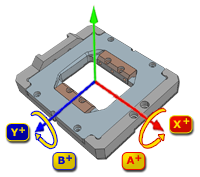
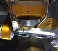 Generally, the two rotary axes that comprise a 5-axis machine are the A-axis, which rotates around the linear X-axis and the B-axis, which rotates around the linear Y-axis of a machine. Depending on configuration, one of the rotary axes should provide a full 360 degrees of rotation, while the other will be limited to an angular range. The limits of this rotational axis is governed by internal construction characteristics and in large part by part geometry and the machines external components such as; fixture configuration, coolant nozzles, spindle geometry, Z-axis head dimensions and the like.
Although a machine manufacturer my provide a specification for theoretical rotary axis operational range, in practical terms it is likely other elements will limit it actual range which may limit its use or in some cases, without sufficient CAM software collision detection or verification capability, result in machine, part and tool mechanical interference - potentially causing damage to all involved elements.
Generally, the two rotary axes that comprise a 5-axis machine are the A-axis, which rotates around the linear X-axis and the B-axis, which rotates around the linear Y-axis of a machine. Depending on configuration, one of the rotary axes should provide a full 360 degrees of rotation, while the other will be limited to an angular range. The limits of this rotational axis is governed by internal construction characteristics and in large part by part geometry and the machines external components such as; fixture configuration, coolant nozzles, spindle geometry, Z-axis head dimensions and the like.
Although a machine manufacturer my provide a specification for theoretical rotary axis operational range, in practical terms it is likely other elements will limit it actual range which may limit its use or in some cases, without sufficient CAM software collision detection or verification capability, result in machine, part and tool mechanical interference - potentially causing damage to all involved elements.
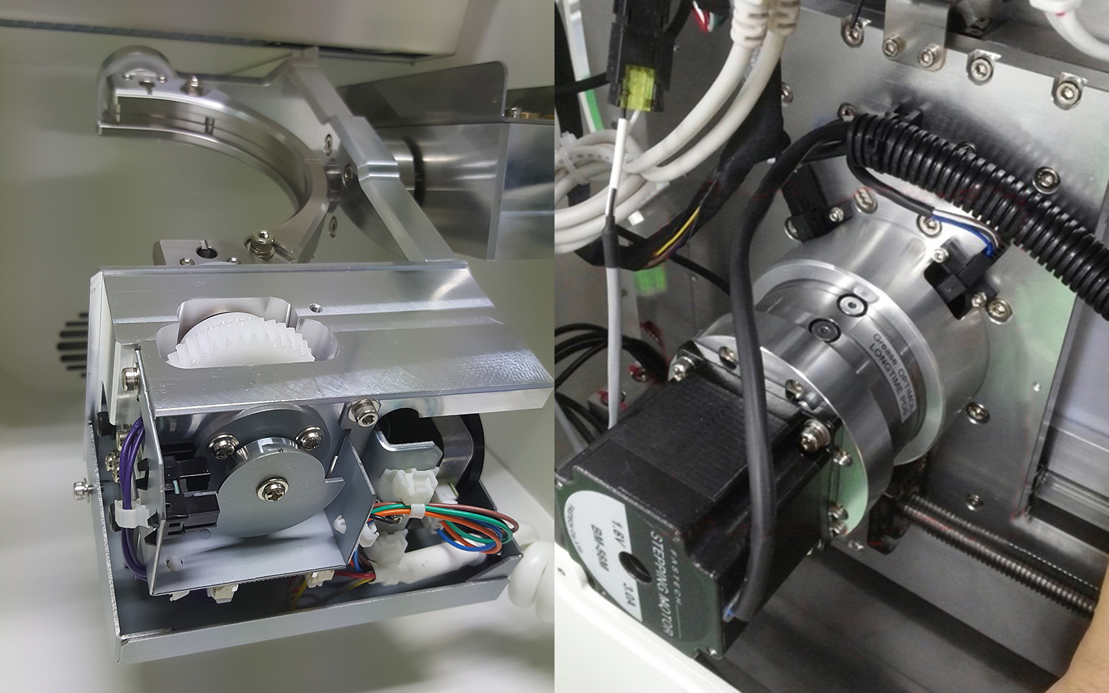
Gear Reduction
A gear reduction drive assembly is utilized to provide the required power to a 5-axis machine’s rotary axes by changing the ratio of the rotation of two moving parts. The performance of the machines rotary drives is in a large part determined by this reduction drive. Key factors to consider include:
- Reduction ratios and gear materials.
- Backlash reduction.
- Drive mass, inertia, acceleration and
velocity. - Losses, efficiency & torque.
The interface between the motor and the axis rotary assembly must be of high precision and made of high-strength materials with high resistance to wear and slippage.
Fixture/Workpiece Support
Fixtures should be of high-precision, constructed of high strength steel and be fully-supported on both ends to assure accuracy, eliminate vibration to provide complete stability. Good jigs and fixtures provide:
- A higher degree of positioning
precision and repeatability. - A greater accuracy for the positioning
of precise hole centers. - Tighter tolerances at micron levels
with higher-quality fit & finish. - Increased cutting tool life.
- Preserve gingival margin integrity.
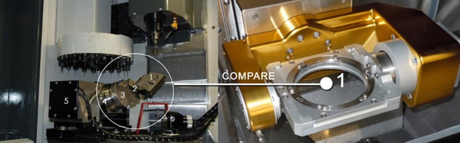
Tolerance Stack
The typical rotary configuration utilized in dental milling machines consists of a trunnion with an A- and B-axis part rotation assembly mounted in the XY In order to multi-axis motion—it is necessary to "stack" each additional axis on top of another.’
- Each "stack" adds a point of
connection or fastening. - Each connection can increase the
chance of positioning errors. The
further out in the stack, the weaker
each element of the added axis
becomes. -
The machine and spindle together
need the capability to contour fast
and accurately at high cutting rates.
As the “stack increases, achieving
stability and dynamic accuracy
becomes extremely difficult.

- Address: 29627 West Tech Dr.
Wixom, MI 48393 - Toll Free: + 1 (855) 687 7941
- Office: + 1 (248) 926 8810
- Fax: + 1 (248) 926 9085
- Email: info@axsysinc.com
Recent Posts

Axsys Dental Solutions Expands Product Portfolio
Axsys Dental Solutions Announces New Line of PMMA CAD/CAM Discs & Acrylic Teeth
Axsys Dental Solutions Expands Product Portfolio
Axsys Dental Solutions Announces New Line of High Translucency Zirconiauseful links
- Whitepaper: Construction
Characteristics of an Effective Dental
Milling Machine - 10 Questions to Ask Before
Purchasing a New Dental Milling
Machine - Axsys Dental Solutions Personal
Care Support Program - Axsys Dental Solutions Corporate
Datasheet - ROI Calculator: Restorative
- ROI Calculator: Custom Abutments